Kerf Width in Modern Laser Cutting: Engineering Precision, Material Efficiency, and the Role of Advanced Machine Design
Abstract
Kerf width—the material removed by a cutting beam—is often overlooked in production planning, yet it directly affects part accuracy, nesting density, and total material yield. In laser cutting, kerf is not a fixed parameter; it depends on laser power, focal position, assist gas pressure, and machine rigidity. This article examines the physical determinants of kerf width in fiber and CO₂ laser systems, presents comparative data across power classes and materials, and discusses how machine builders like ROCLAS® MACHINERY CO., LTD. address kerf control through structural design and motion precision. Understanding kerf behavior enables fabricators to reduce scrap, improve nesting efficiency, and achieve tighter tolerances without post-processing.
---
1. Why Kerf Width Matters More Than You Think
In sheet metal fabrication, few parameters are as deceptively simple—and as consequential—as kerf width. Every cut removes a narrow strip of material. Multiply that strip by thousands of parts per shift, and the cumulative material loss becomes a measurable cost. In high-volume industries such as automotive stamping, kitchen equipment manufacturing, or steel structure fabrication, even a 0.1 mm reduction in kerf can translate to significant annual savings in raw material.
Beyond economics, kerf width influences part fit-up in assemblies. A 1.0 mm kerf on a 6 mm carbon steel plate yields a different edge geometry than a 0.8 mm kerf under the same nominal conditions. For precision components—such as those used in aerospace brackets or medical device frames—consistent kerf is essential for maintaining dimensional tolerances.
Kerf width is not a machine constant. It varies with laser power, focal position, assist gas pressure, material type, thickness, and cutting speed. More subtly, it is affected by the dynamic stiffness of the machine structure. A gantry that deflects under acceleration or thermal load will produce inconsistent kerf along the cut path. This is where machine design—specifically, the rigidity of the frame and the precision of the motion system—becomes a first-order factor.
---
2. Determinants of Kerf Width in Laser Cutting
2.1 Laser Power and Spot Size
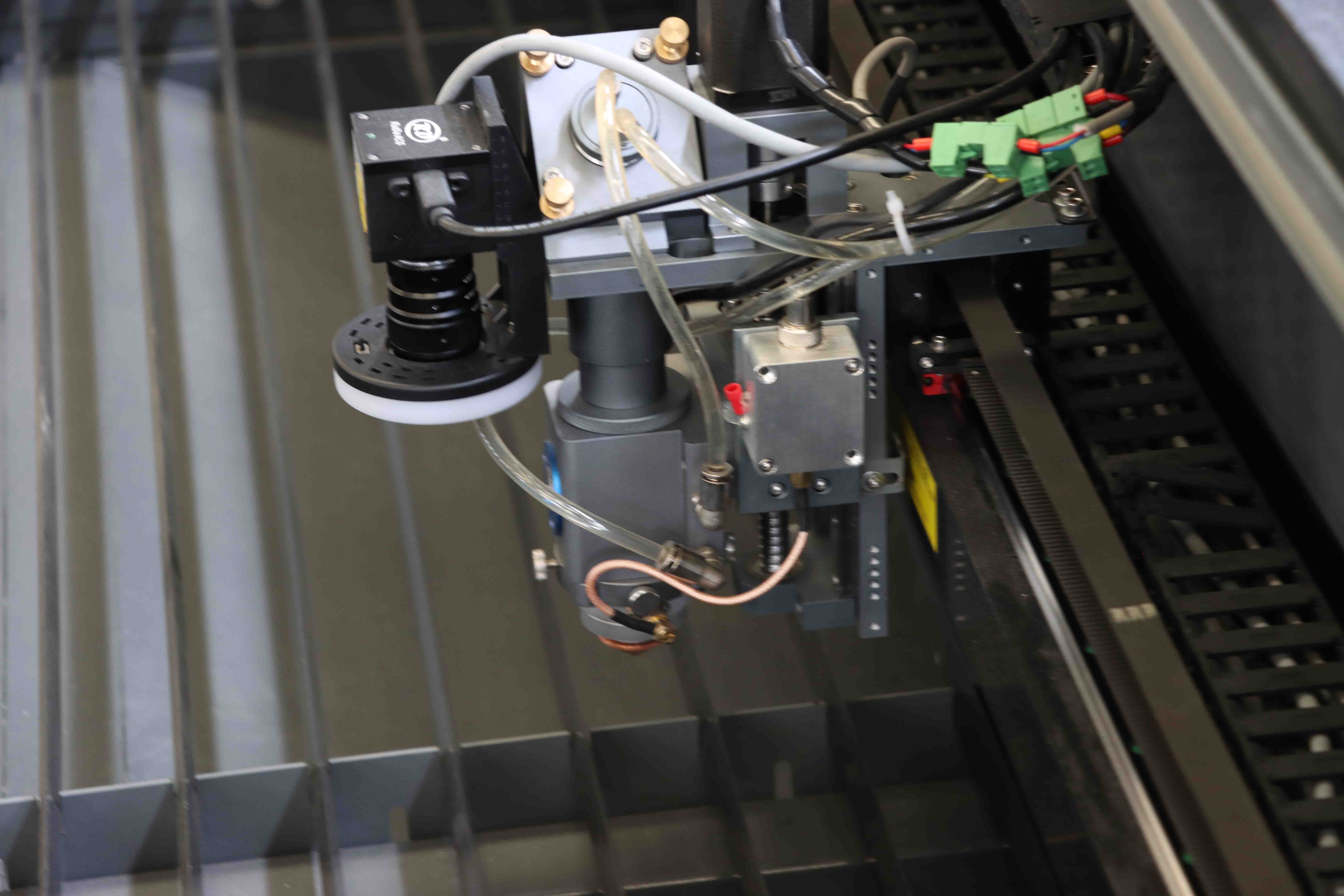
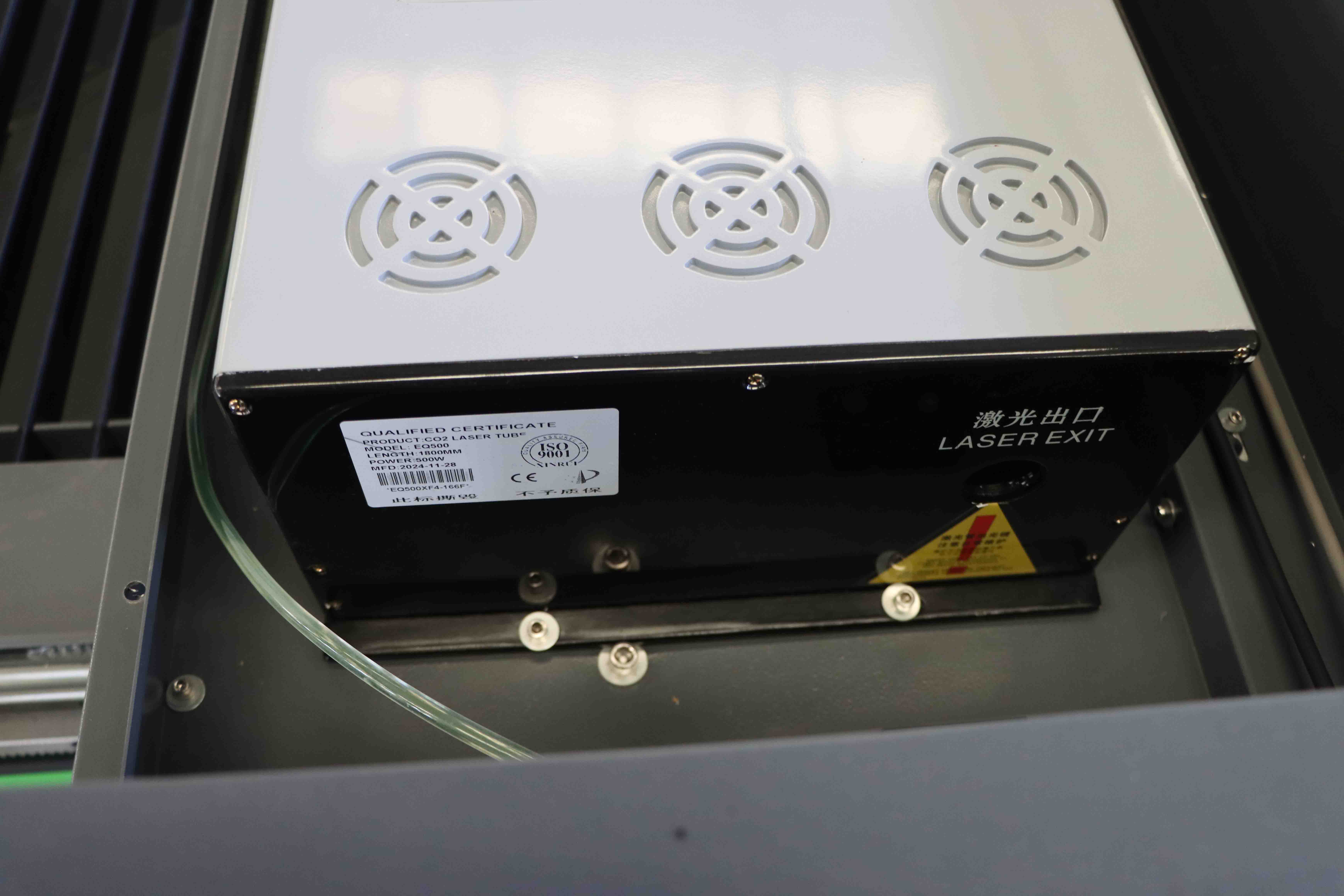
The fundamental relationship is straightforward: higher power density at the focal point produces a narrower kerf, provided the beam quality is maintained. Fiber lasers, with their shorter wavelength (typically 1070 nm) and superior beam quality compared to CO₂ lasers, can achieve smaller focal spots for a given focal length. A typical fiber laser cutting 1 mm stainless steel may produce a kerf of 0.15–0.25 mm, whereas a CO₂ laser under similar conditions might yield 0.3–0.5 mm.
However, as thickness increases, the kerf necessarily widens. For thick plates (≥10 mm), the kerf can reach 0.5–1.0 mm even with high-power fiber lasers, due to the need for wider nozzle diameters and higher gas flow to eject molten material.
2.2 Assist Gas and Nozzle Geometry
Oxygen-assisted cutting of mild steel produces an exothermic reaction that adds energy to the cut, often resulting in a slightly wider kerf and a rougher edge. Nitrogen or compressed air, used for stainless steel and aluminum, produces a cleaner cut with narrower kerf. Nozzle standoff distance and orifice diameter also play a role; a smaller nozzle orifice concentrates the gas jet but may increase kerf if the gas velocity becomes too high.
2.3 Machine Rigidity and Dynamic Performance
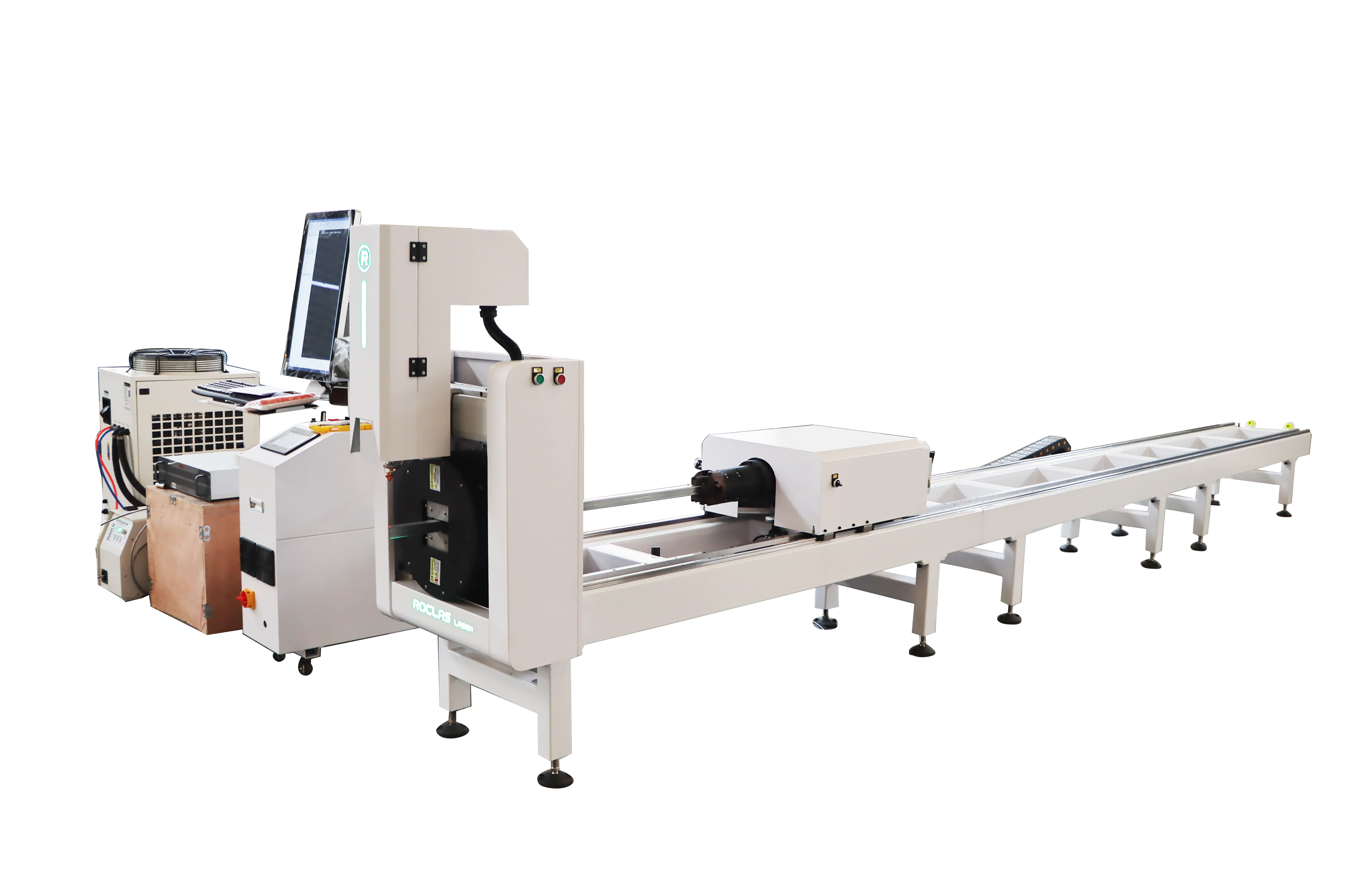
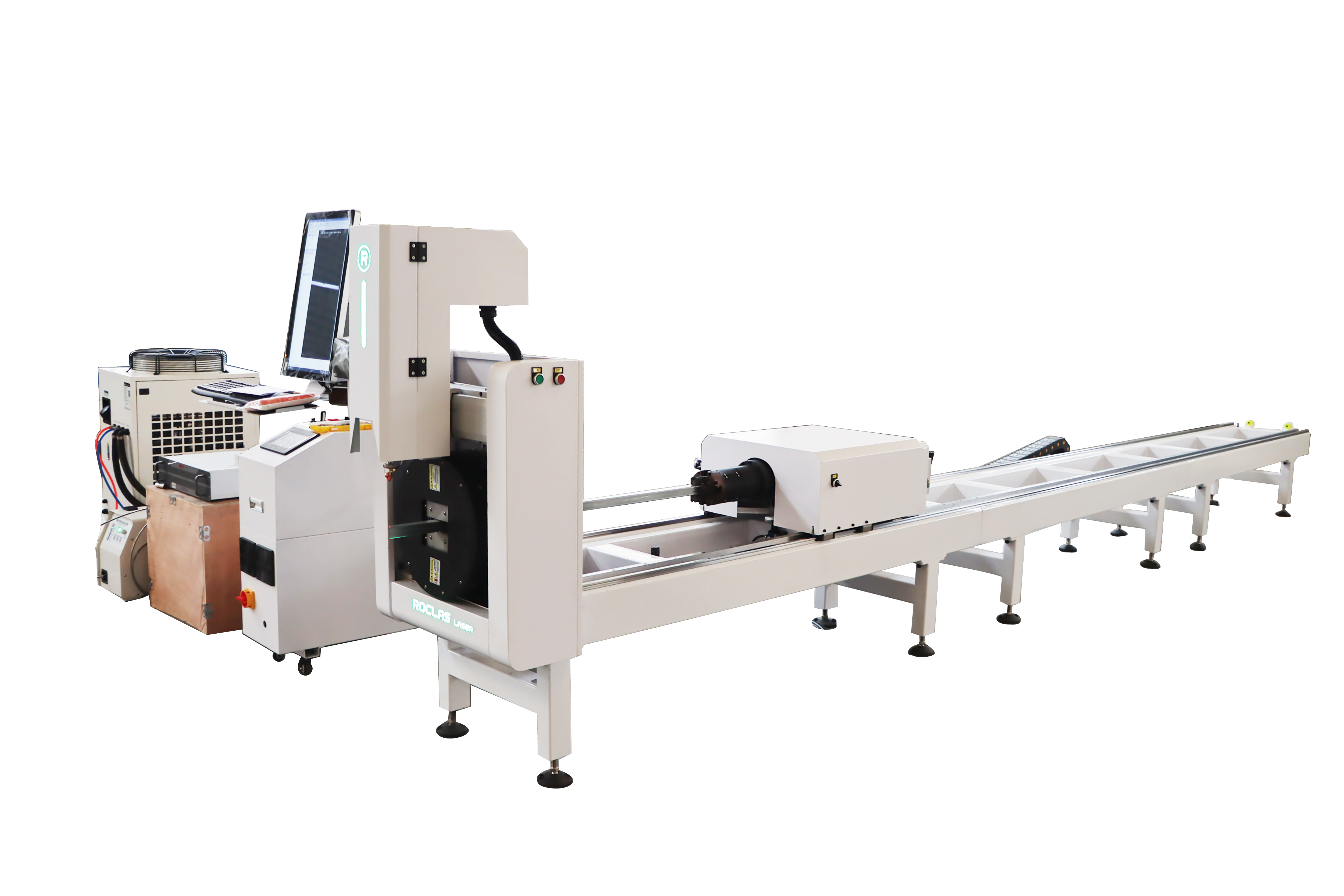
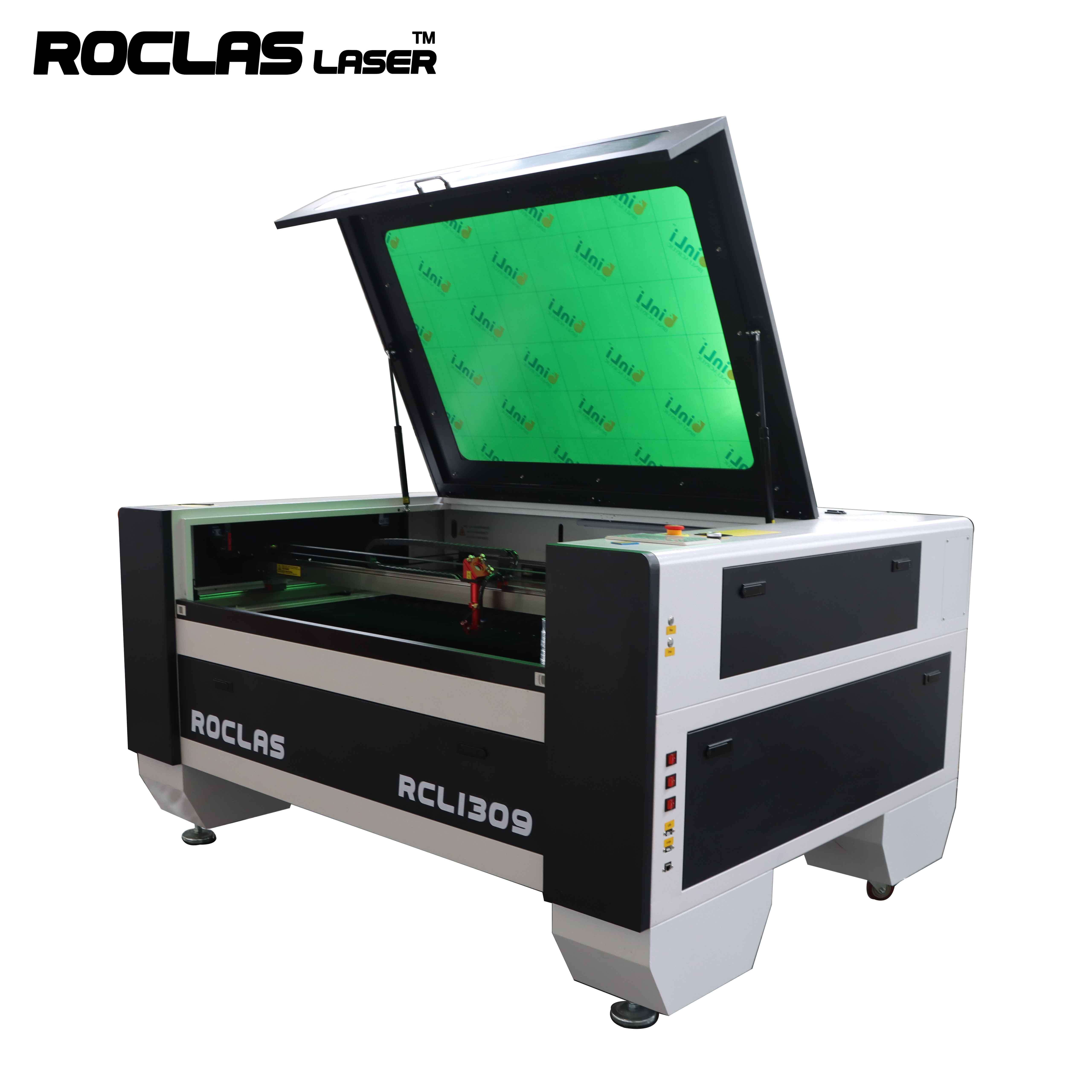
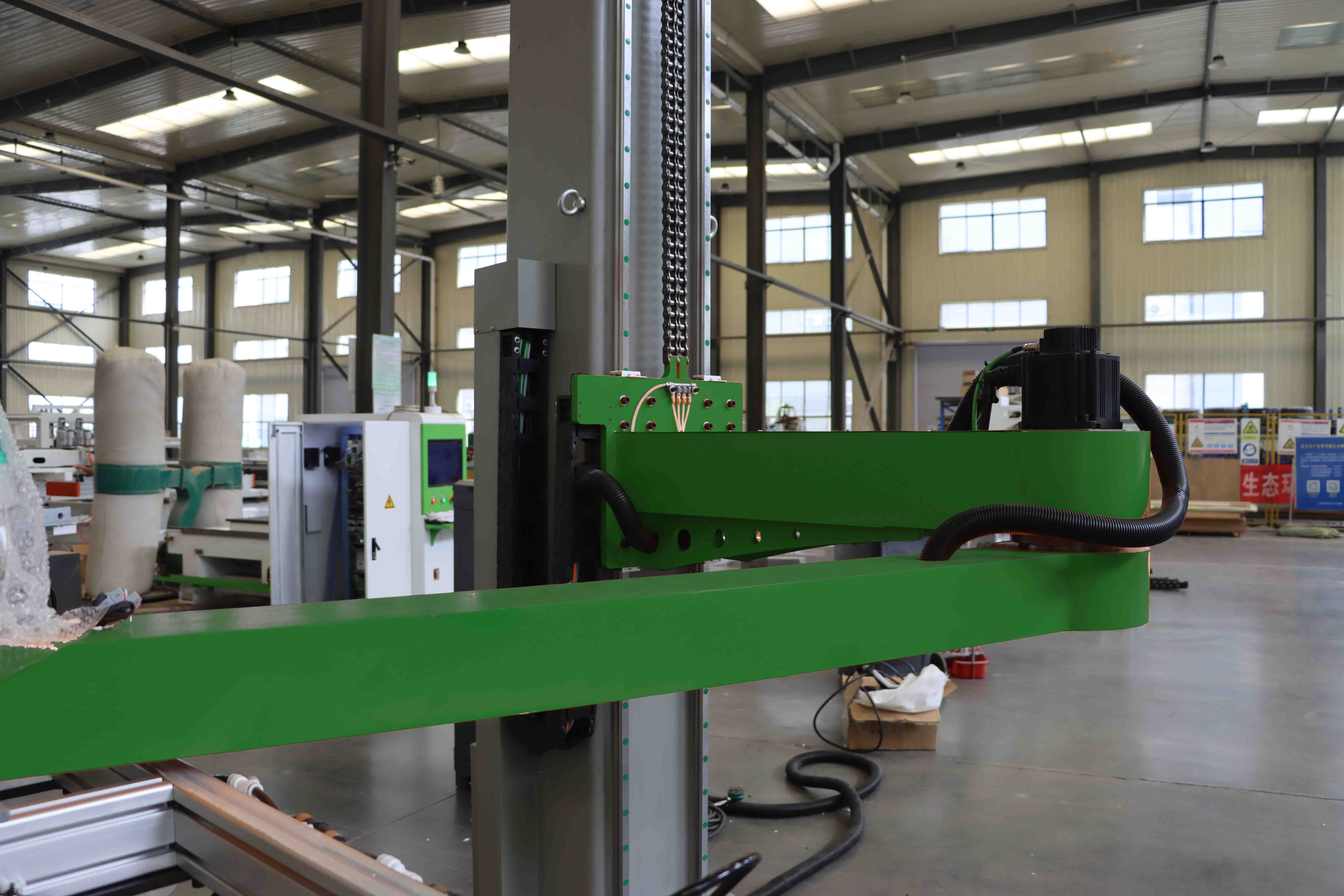
This factor is frequently underestimated. A machine with a heavy-duty steel structure—such as those produced by ROCLAS® MACHINERY CO., LTD. —exhibits minimal deflection under cutting forces and thermal gradients. The company’s industrial-grade frames are machined on CNC five-face machining centers, ensuring that guide rails and rack-and-pinion systems are mounted on truly flat reference surfaces. The result is consistent focal distance across the entire working area, which directly translates to uniform kerf width.
---
3. Kerf Width Data: Comparative Analysis
The following table presents measured kerf widths for common materials and thicknesses, based on data from Fiber laser cutting machines in the 1000W–6000W range, using a Raycus laser source and Cypcut control system. All measurements were taken at optimal cutting speed and gas pressure for each material-laser combination.
| Material | Thickness (mm) | Laser Power (W) | Assist Gas | Typical Kerf Width (mm) | Tolerance (±mm) |
|----------|----------------|-----------------|------------|------------------------|-----------------|
| Carbon Steel (mild) | 1.0 | 1000 |
Get a Quote
Regardless of whether you require general advice or specific support, we are happy to help you.
Recent Post
-
 Robotic Arm Laser Systems: Redefining Precision and Flexibility in Industrial ManufacturingAbstractThe integration of robotic arms with laser processing technologies represents a paradigm s...2026-07-06 16:30:57
 -
 The Ultimate Guide to High-Performance Fiber Laser Metal Cutting MachinesIntroductionFiber laser metal cutting machines have revolutionized the manufacturing industry with...2025-06-24 19:56:52
 -
 Understanding the Key Differences Between Fiber Laser and CO2 LaserIn the world of laser cutting and engraving, two types of lasers dominate the industry fiber laser...2025-03-30 09:31:59
 -
 The Ultimate Guide to Programmable Laser Cutters Revolutionizing Precision and EfficiencyIntroductionIn the realm of modern manufacturing and design, programmable laser cutters have emerg...2025-03-29 09:32:00
 -
 The Ultimate Guide to Steel Laser Cutting Techniques, Benefits, and ApplicationsIntroductionSteel laser cutting has revolutionized the manufacturing and fabrication industries, o...2025-03-24 08:31:07
 -
 Why Choose Roclas Fiber Laser Cutting for PED Components?IntroductionLaser cutting technology has revolutionized metal fabrication, offering unmatched prec...2025-06-16 07:49:19